


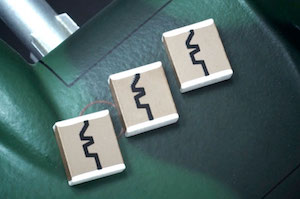
N2200 Fuze Capacitors
Table of Maximum Capacitance Values for Custom Chips
Class I - N2200 (R) Dielectric
The following table represents our standard listing of Pulse Energy/Detonation (Fuze) capacitors produced from our proprietary N2200 dielectric formulation. In addition to the below listed standard case sizes, WCI is ideally situated to custom fabricate alternative size, thickness and/or voltage ratings per individual requirements. Should you not find what you are looking for please call the factory.
Produced according to meticulously defined standards, all parts are then conditioned at elevated
temperature and voltage. 100% of all lots are screened for conformance to stated performance
criteria. All units are tested to MIL-PRF-49467 however
customer required screening can also be accommodated.
Our high reliability line of N2200 capacitors are specifically designed to withstand the rigors of single or multiple pulse firings.
A temperature coefficient of 2200 PPM is standard and typical results are detailed below. Common applications include aerospace, defense, pulse energy detonation and higher end consumer needs requiring a greater degree of safety/reliability not usually found in “cots” parts.
DF= .15 Max
N2200 Fuze Capacitors (Case sizes in inches)
(Also see Class I Dielectric charts, "R" material, for other maximum capacitance values.)| SIZE | 2838 | 3840 | 4565 | 6964 | 8840 | 13060 |
| LENGTH-NOM | 0.280 | 0.380 | 0.450 | 0.690 | 0.880 | 1.300 |
| WIDTH-NOM | 0.380 | 0.400 | 0.650 | 0.650 | 0.400 | 0.600 |
| MAX-THICK | 0.275 | 0.275 | 0.300 | 0.400 | 0.300 | 0.300 |
| SIZE / VOLTAGE | 2838 | 3840 | 4565 | 6964 | 8840 | 13060 |
| 500V | 154 | 184 | 394 | 564 | ||
| 1000V | 104 | 124 | 274 | 474 | ||
| 2000V | 333 | 473 | 184 | 224 | ||
| 3000V | 183 | 223 | 473 | 124 | ||
| 4000V | 682 | 822 | 223 | 473 | 153 | 683 |
| 5000V | 392 | 472 | 103 | 223 | 103 | 333 |
| 7000V | 562 | 103 | 472 | 153 | ||
| 10,000V | 272 | 562 | 272 | 822 |
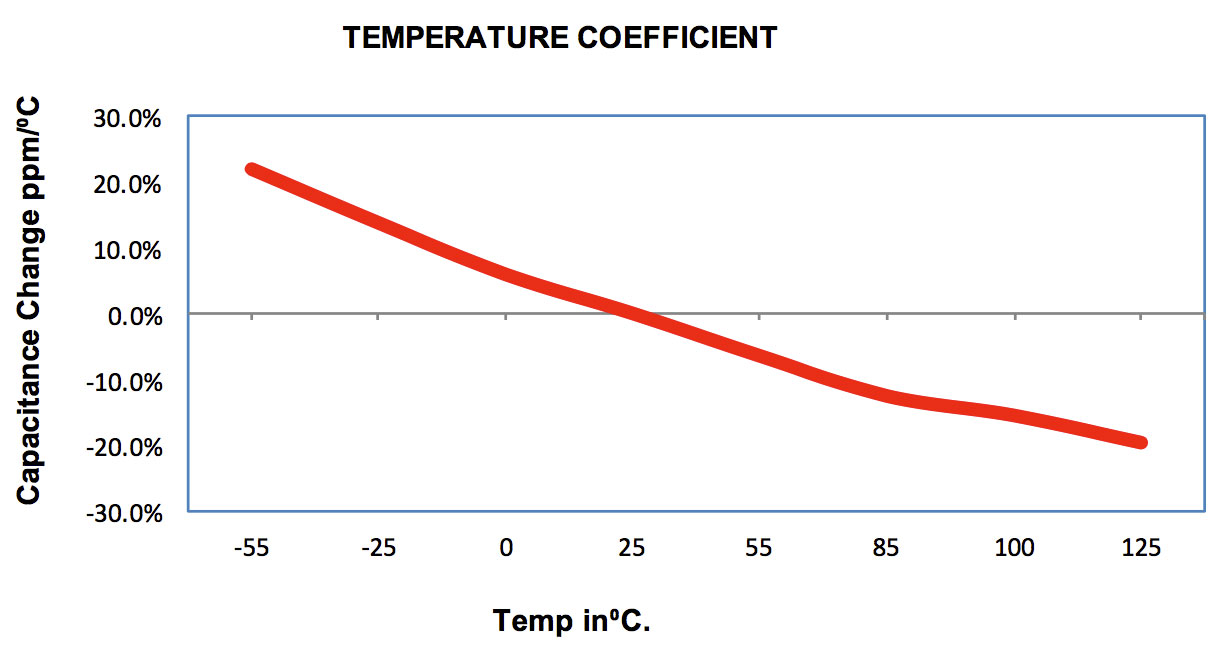
Temperature Coefficient
N2200 (R) Pulse Energy/Fuze Capacitor
| Material: | N2200 (R) Pulse Energy/Fuze Capacitor |
| Operation Temperature Range: | -55°C to 125°C. |
| Temperature Coefficient: | -2200ppm/°C typical, tolerance per EIA-198 |
| Dissipation Factor: | 0.15% max at 25°C. |
| Insulation Resistance: |
at 25°C > 100GΩ or 1000MΩμF or whichever is less. at 125°C > 10GΩ or 100MΩμF or whichever is less. |
| Dielectric withstanding Voltage: |
250% for parts ≤250V. x 150% for parts 250V-1KV. 120% for parts >1KV. |
| Aging Rate: | 0% per decade. |
| Testing Parameters: |
1kHz, 1.0 ± 0.2VRMS, 25°C. 1mHz for capacitance ≤ 100pF. |
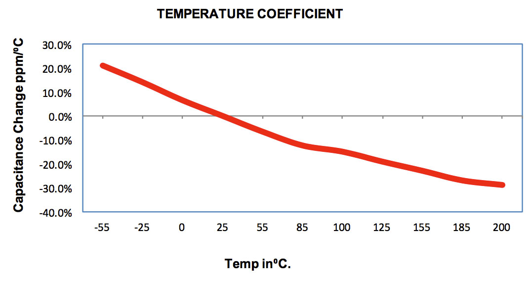
N2200 (R) Hi TEMP 200°C
| Material: | N2200 (R) Hi TEMP 200°C |
| Operation Temperature Range: | -55°C to 200°C. |
| Temperature Coefficient: | -2200ppm/°C typical, tolerance per EIA-198 |
| Dissipation Factor: | 0.15% max at 25°C. |
| Insulation Resistance: |
at 25°C > 100GΩ or 1000MΩμF or whichever is less. at 125°C > 10GΩ or 100MΩμF or whichever is less. at 200°C >1GΩ or 10MΩμF or whichever is less. |
| Dielectric withstanding Voltage: |
250% for parts ≤250V. 150% for parts 250V-1KV. 120% for parts >1KV. |
| Aging Rate: | 0% per decade. |
| Testing Parameters: |
1kHz, 1.0 ± 0.2VRMS, 25°C. 1mHz for capacitance ≤ 100pF. |
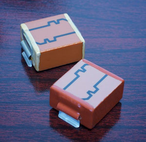
As a safety feature an integrated bleed resistor can be included on the
capacitor. This can either be a single resistive element or dual for redundancy
purposes. Typical resistance values range from 100MΩ to 500MΩ at ±20%.
Although other values and tolerances can be specified. Resistors are stable up to
200°C.
Fuze caps with an integrated bleed resistor will be coated with our clear, high temperature, high voltage and moisture resistant protective coating. All other fuze caps will be coated with our red urethane varnish.
Ordering Information
| Prefix | Case Size | Encapsulation | Dielectric | Capacitance | Tolerance | Termination | Voltage | Suffix |
| SMN | 3840 | T | R | 124 | K | D | 102 | -R300 |
|
SM - Surface Mount SMN - Surface Mount w/ Testing SMS - Special Solder required - Sn95Sb05 |
Chip Size |
E = E Lead G = Gull Lead J = J Lead L = L Lead T = Tab Lead |
N = NPO R = N2200 X = X7R See Dielectric Characteristics for full list |
Capacitance Value Code in pF 1st two digits significant, 3rd the power of ten i.e.: 102 = 1000pF |
F = ±1% G = ±2% J = ±5% K = ±10% M = ±20% Z = +80%/-20% V = +100% |
A = Ag D = PdAg |
Voltage Code 1st two digits significant, 3rd the power of ten i.e. 102 = 1000V |
-A MIL-PRF-49467 -NM No Marking -NC No Coating -R#### = Bleed Resistor in MΩ -X### = Special Thickness |
Dielectric Codes
| Dielectric Code | Material |
Temperature Coefficient Please see Dielectric Characteristics for more information |
| N | COG/NPO | -55°/+125°C |
| N | COG/NPO | Hi Temp -55°/+250°C |
| R | N2T | -55°/+125°C/ ±500pm |
| R | N2T | Hi Temp -55°/+250°C |
| X | X7R/BR | BR -55°/+125°C |
| X | X7R/BR | Hi Temp -55°/+250°C |
| Y | Y5V | Y5V -30°/+85°C |
Prefixes
| Prefix | Description |
| WC | Standard |
| WCN |
Non standard Requirements High Temperature High Reliability |
| WCR | RoHS Compliant |
| HT | High Temperature (Potted Units) |
| HTN | High Temp w/ High Reliability Testing (Potted Units) |
| SM | Surface Mount |
| SMN | Surface Mount with High Reliability Testing |
| SMS | Special Solder required (Sn95Sb05) |
Capacitance Tolerance Codes
| Code | Tolerance |
| F | ± 1% |
| G | ± 2% |
| J | ± 5% |
| K | ± 10% |
| M | ± 20% |
| Z | +80%/-20% |
| V | + 100% |
Suffixes
| Suffix | Description |
| -A | MIL-PRF-49467 |
| -NM | No Marking |
| -NC | No Coating |
| -R ### | Bleed Resistor |
| -X### | Special Thickness |