


High Temperature Capacitors
All our Class I NPO / N2200 and Class II X7R dielectrics are capable of 200°C performance. Please see those case sizes and specify High Temp required.
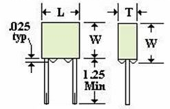
"P" Square - Potted Case - Radial Lead.
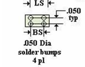
"B" with solder standoffs.
Leads - 22 AWG Cu/Ni/SnPb Sn96 Hot Solder Dipped.
Voltage - As specified, rated to 200°C
Voltage - As specified, rated to 200°C
Shell Material
"B" Off White Vectra Per MIL-M-24519C
"P" Black Epoxy Per MIL-M-24325MEC
HT3030, HT4040, HT5050
Tcc - X7R= -45% max at 200°C
-30% max at 175°C
NPO= 30 ppm/°C max
IR= 25°C= 1000mΩ-μFmin
125°C= 100mΩ-μFmin
150°C= 10mΩ-μFmin
200°C= 1mΩ-μFmin
-30% max at 175°C
NPO= 30 ppm/°C max
IR= 25°C= 1000mΩ-μFmin
125°C= 100mΩ-μFmin
150°C= 10mΩ-μFmin
200°C= 1mΩ-μFmin
| Case | L ±.005 | W ±.005 | W/B incl. Bump | L.S. ±.015 | Bump Space |
| HT2020P | .200 | .200 | --- | .200 | --- |
| HT3030P | .300 | .300 | --- | .200 | --- |
| HT3030B | .300 | .300 | .330 | .200 | .100 |
| HT4040P | .400 | .400 | --- | .300 | --- |
| HT4040B | .400 | .400 | .430 | .300 | .200 |
| HT5050P | .500 | .500 | --- | .400 | --- |
| HT5050B | .500 | .500 | .530 | .400 | .300 |
HT2020 - No solder bumps available. Lead form gives .025" typical offset.
HT3030, 4040, and 5050 - available with .025" solder stand off bumps (B option) for
cleaning and inspection of solder joints.
Table of Maximum Capacitance Values for High Temperature Line
Potted Shells @thickness .100" and .150"
*Note: Shells available in thickness > .150" for higher values, please consult factory.
| 500V | 1KV | 2KV | |||||
| Thk Max | Mtl | .100" | .150" | .100" | .150" | .100" | .150" |
| 2020 | NPO | 222 | 332 | 102 | 152 | 331 | 561 |
| N2200 | 822 | 123 | 392 | 562 | 122 | 182 | |
| X7R | 223 | 333 | 682 | 103 | 152 | 272 | |
| 3030 | NPO | 822 | 123 | 392 | 562 | 122 | 182 |
| N2200 | 273 | 473 | 123 | 223 | 472 | 682 | |
| X7R | 683 | 124 | 183 | 393 | 562 | 103 | |
| 4040 | NPO | 183 | 273 | 822 | 123 | 272 | 472 |
| N2200 | 683 | 104 | 273 | 473 | 103 | 153 | |
| X7R | 154 | 274 | 563 | 823 | 123 | 223 | |
| 5050 | NPO | 333 | 394 | 153 | 223 | 472 | 682 |
| N2200 | 104 | 154 | 473 | 823 | 153 | 273 | |
| X7R | 274 | 474 | 823 | 154 | 183 | 393 | |
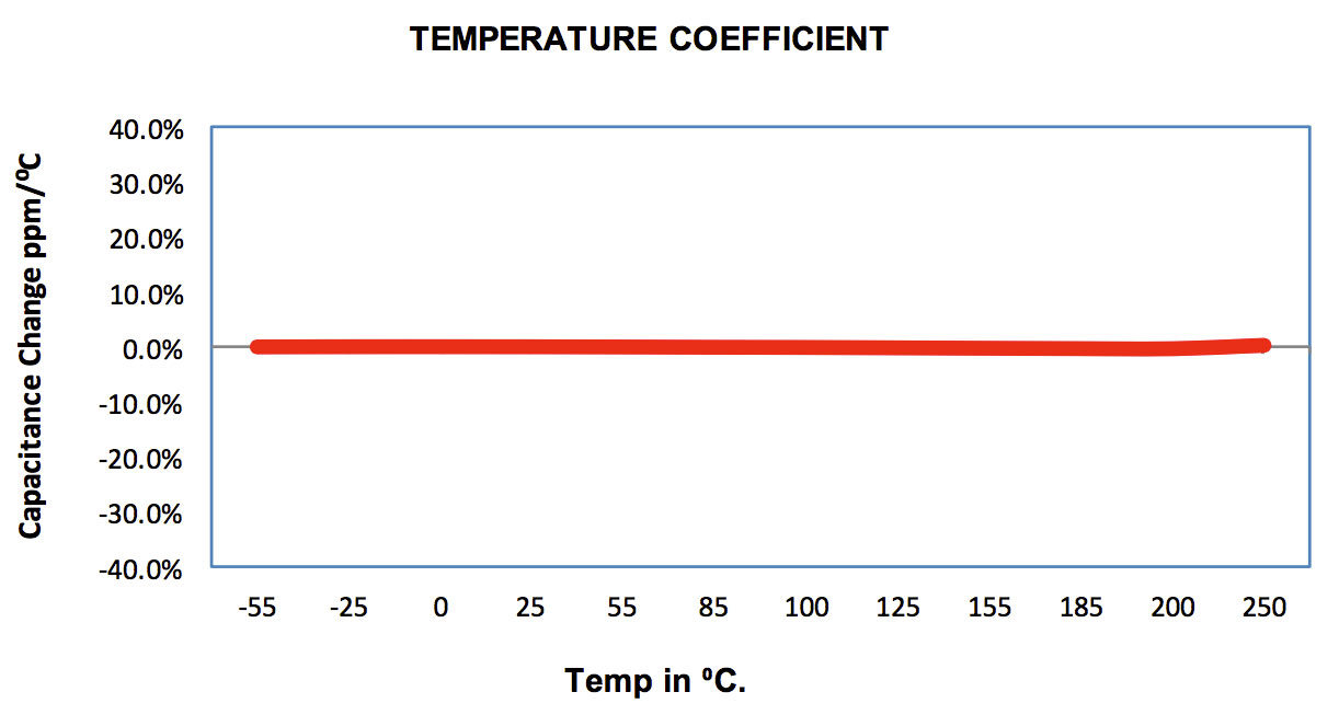
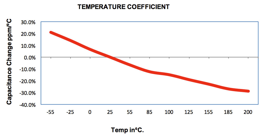
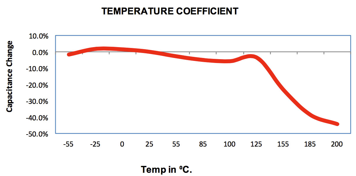
Temperature Coefficient
COG/NPO Stable High Temperature Up to 250°C
| Material: | COG/NPO Stable High Temperature Up to 250°C |
| Operation Temperature Range: | -55°C to 250°C. |
| Temperature Coefficient: | ± 30ppm/°C. |
| Dissipation Factor: | 0.1% max at 25°C. |
| Insulation Resistance: |
at 25°C > 100GΩ or 1000MΩμF or whichever is less. at 125°C > 10GΩ or 100MΩμF or whichever is less. at 250°C > 1GΩ or 10MΩμF or whichever is less. |
| Dielectric withstanding Voltage: |
250% for parts ≤250V. 150% for parts 250V-1KV. 120% for parts >1KV. |
| Aging Rate: | 0% per decade. |
| Testing Parameters: |
1kHz, 1.0 ± 0.2VRMS, 25°C. 1mHz for capacitance ≤ 100pF. |
N2200 (R) Hi TEMP 200°C
| Material: | N2200 (R) Hi TEMP 200°C |
| Operation Temperature Range: | -55°C to 200°C. |
| Temperature Coefficient: | -2200ppm/°C typical, tolerance per EIA-198 |
| Dissipation Factor: | 0.15% max at 25°C. |
| Insulation Resistance: |
at 25°C > 100GΩ or 1000MΩμF or whichever is less. at 125°C > 10GΩ or 100MΩμF or whichever is less. at 200°C >1GΩ or 10MΩμF or whichever is less. |
| Dielectric withstanding Voltage: |
250% for parts ≤250V. 150% for parts 250V-1KV. 120% for parts >1KV. |
| Aging Rate: | 0% per decade. |
| Testing Parameters: |
1kHz, 1.0 ± 0.2VRMS, 25°C. 1mHz for capacitance ≤ 100pF. |
High Temp X7R (X) Class II (200°C)
| Material: | High Temp X7R (X) Class II (200°C) |
| Operation Temperature Range: | -55°C to 200°C. |
| Temperature Coefficient: | +15% -45% Max |
| Cap Drop at 200°C: | -45% Max |
| Dissipation Factor: | 2.5% max at 25°C. |
| Insulation Resistance: |
at 25°C > 100GΩ or 1000MΩμF or whichever is less. at 125°C > 10GΩ or 100MΩμF or whichever is less. at 200°C >1GΩ or 10MΩμF or whichever is less. |
| Dielectric withstanding Voltage: |
250% for parts ≤250V. 150% for parts 250V-1KV. 120% for parts >1KV. |
| Aging Rate: | <2% per decade. |
| Testing Parameters: |
1kHz, 1.0 ± 0.2VRMS, 25°C. 1mHz for capacitance ≤ 100pF. |
Ordering Information
| Prefix | Case Size | Encapsulation | Dielectric | Capacitance | Tolerance | Termination | Voltage |
| HT | 3030 | B | X | 124 | K | D | 102 |
|
HT - High Temp (Potted Units) HTN - High Temp w/ Testing (Potted Units) WCN - High Temp (Dipped Units) |
Chip Size |
P = Square Shell B = Shell w/ Solder Bumps |
N = NPO R = N2200 X = X7R See Dielectric Characteristics for full list |
Capacitance Value Code in pF 1st two digits significant, 3rd the power of ten i.e.: 102 = 1000pF |
F = ±1% G = ±2% J = ±5% K = ±10% M = ±20% Z = +80%/-20% V = +100% |
A = Ag D = PdAg C = Leads w/ SnPb Coating |
Voltage Code 1st two digits significant, 3rd the power of ten i.e. 102 = 1000V |
Dielectric Codes
| Dielectric Code | Material |
Temperature Coefficient Please see Dielectric Characteristics for more information |
| N | COG/NPO | -55°/+125°C |
| R | N2T | -55°/+125°C/ ±500pm |
| B | X7R/BR | BR -55°/+125°C |
| X | BX/MIL | BX -55°/+125°C VC -25% max |
| Y | Y5V | Y5V -30°/+85°C |
Prefixes
| Prefix | Description |
| WC | Standard |
| WCN |
Non standard Requirements High Temperature (dipped units) High Reliability |
| WCR | RoHS Compliant |
| HT | High Temperature (Potted Units) |
| HTN | High Temp w/ High Reliability Testing (Potted Units) |
| SM | Surface Mount |
| SMN | Surface Mount with High Reliability Testing |
Capacitance Tolerance Codes
| Code | Tolerance |
| F | ± 1% |
| G | ± 2% |
| J | ± 5% |
| K | ± 10% |
| M | ± 20% |
| Z | +80%/-20% |
| V | + 100% |
Suffixes
| Suffix | Description |
| -A | MIL-PRF-49467 |
| -NM | No Marking |
| -NC | No Coating |
| -X### | Special Thickness |