


Class II High Reliability Chip (X7R)
The following table represents our standard listing of MLC’s produced from our stable EIA Class II X7R dielectric. In addition to the below listed standard case sizes, WCI is ideally situated to custom fabricate alternative size, thickness and/or voltage ratings per individual requirements. Should you not find what you are looking for please call the factory.
Produced according to meticulously defined standards, all parts are then conditioned at elevated temperature and voltage. 100% of all lots are screened for conformance to stated performance criteria. All units are tested to MIL-PRF-49467 however customer required screening can also be accommodated.
Our high reliability line of class II X7R capacitors are very well suited to applications allowing for predictable changes in electrical properties given time, temperature and voltage. A temperature coefficient of ±15% is standard and typical results are detailed below. Common applications include aerospace, defense, pulse energy detonation and higher end consumer needs requiring a greater degree of safety/reliability (not usually found in “cots” parts).
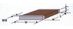
Case Sizes (in inches)
 |
 |
 |
 |
 |
 |
 |
 |
|
| SIZE | 1210 | 1515 | 1812 | 1825 | 2020 | 2225 | 2520 | 3530 |
| LENGTH-NOM | 0.120 | 0.150 | 0.180 | 0.180 | 0.200 | 0.220 | 0.250 | 0.350 |
| WIDTH-NOM | 0.100 | 0.150 | 0.120 | 0.250 | 0.200 | 0.250 | 0.200 | 0.300 |
| THICK-MAX | 0.100 | 0.150 | 0.200 | 0.200 | 0.200 | 0.250 | 0.250 | 0.250 |
| SIZE | 4040 | 4540 | 5550 | 6560 | 7565 | 8840 | 11050 | 13060 |
| LENGTH-NOM | 0.400 | 0.450 | 0.550 | 0.650 | 0.750 | 0.880 | 1.100 | 1.300 |
| WIDTH-NOM | 0.400 | 0.400 | 0.500 | 0.600 | 0.650 | 0.400 | 0.500 | 0.600 |
| THICK-MAX | 0.300 | 0.300 | 0.300 | 0.300 | 0.300 | 0.300 | 0.300 | 0.300 |
Dimensions are ±5% length and width or .015;, whichever is greater.
MB=.005/.040
Note: These are standard sizes. We can manufacture any size required. Please consult factory for special builds.
Max Capacitance Table*
| SIZE | 1210 | 1515 | 1812 | 1825 | 2020 | 2225 | 2520 | 3530 |
| 250V | 473 | 104 | 104 | 224 | 154 | 274 | 154 | |
| 500V | 223 | 563 | 563 | 154 | 104 | 184 | 124 | 394 |
| 1000V | 562 | 183 | 183 | 563 | 473 | 823 | 563 | 184 |
| 2000V | 102 | 392 | 392 | 153 | 123 | 183 | 153 | 473 |
| 3000V | 152 | 152 | 392 | 332 | 472 | 392 | 183 | |
| 4000V | 152 | 562 | ||||||
| 5000V | 102 | 472 | ||||||
| 7000V | 182 | |||||||
| 10000V |
| SIZE | 4040 | 4540 | 5550 | 6560 | 7565 | 8840 | 11050 | 13060 |
| 250V | ||||||||
| 500V | 474 | 564 | ||||||
| 1000V | 274 | 334 | 474 | 105 | 105 | |||
| 2000V | 683 | 823 | 154 | 224 | 274 | |||
| 3000V | 223 | 223 | 473 | 823 | 104 | |||
| 4000V | 822 | 103 | 223 | 333 | 393 | 183 | 473 | 563 |
| 5000V | 392 | 562 | 822 | 153 | 183 | 822 | 223 | 223 |
| 7000V | 122 | 472 | 562 | 103 | 682 | 562 | 153 | 183 |
| 10000V | 102 | 122 | 222 | 392 | 392 | 332 | 562 | 822 |
*Note: Maximum capacitance values are shown above as 3 digit code: 2 significant figures followed by the no. of zeros e.g. 153 = 15,000pF. R denotes decimal e.g. 1R5 = 1.5pF
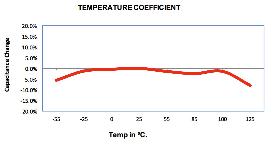
Temperature Coefficient
X7R (X)
| Material: | X7R (BR) |
| Operation Temperature Range: | -55°C to 125°C. |
| Temperature Coefficient: | ±15% |
| Dissipation Factor: | 2.5% max at 25°C. |
| Insulation Resistance: |
at 25°C > 100GΩ or 1000MΩμF or whichever is less. at 125°C > 10GΩ or 100MΩμF or whichever is less. |
| Dielectric withstanding Voltage: |
250% for parts ≤250V. 150% for parts 250V-1KV. 120% for parts >1KV. |
| Aging Rate: | <2% per decade. |
| Testing Parameters: |
1kHz, 1.0 ± 0.2VRMS, 25°C. 1mHz for capacitance ≤ 100pF. |
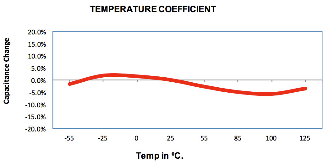
X7R (X)
| Material: | X7R (BX) |
| Temperature Coefficient: | ±15% |
| Voltage Coefficient: | -25% Max. |
| Operation Temperature Range: | -55°C to 125°C. |
| Dissipation Factor: | 2.5% max at 25°C. |
| Insulation Resistance: |
at 25°C > 100GΩ or 1000MΩμF or whichever is less. at 125°C > 10GΩ or 100MΩμF or whichever is less. |
| Dielectric withstanding Voltage: |
250% for parts ≤250V. 150% for parts 250V-1KV. 120% for parts >1KV. |
| Aging Rate: | <2% per decade. |
| Testing Parameters: |
1kHz, 1.0 ± 0.2VRMS, 25°C. 1mHz for capacitance ≤ 100pF. |
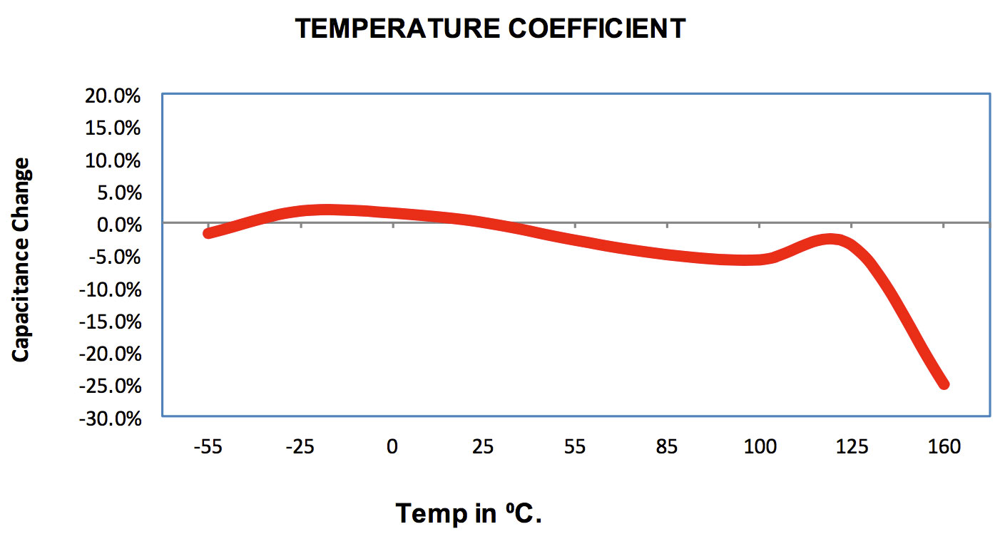
X8R (U) High Temperature
| Material: | X8R High Temperature |
| Operation Temperature Range: | -55°C to 160°C. |
| Temperature Coefficient: | + 15% -25% Max |
| Dissipation Factor: | 2.5% max at 25°C. |
| Insulation Resistance: |
at 25°C > 100GΩ or 1000MΩμF or whichever is less. at 125°C > 10GΩ or 100MΩμF or whichever is less. at 160°C > 1GΩ or 10MΩμF or whichever is less. |
| Dielectric withstanding Voltage: |
250% for parts ≤250V. 150% for parts 250V-1KV. 120% for parts >1KV. |
| Aging Rate: | <2% per decade. |
| Testing Parameters: |
1kHz, 1.0 ± 0.2VRMS, 25°C. 1mHz for capacitance ≤ 100pF. |
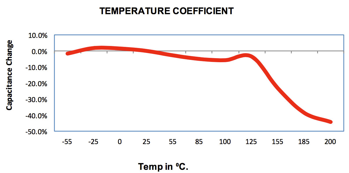
High Temp X7R (X) Class II (200°C)
| Material: | High Temp X7R Class II (200°C) |
| Operation Temperature Range: | -55°C to 200°C. |
| Temperature Coefficient: | +15% -45% Max |
| Cap Drop at 200°C: | -45% Max |
| Dissipation Factor: | 2.5% max at 25°C. |
| Insulation Resistance: |
at 25°C > 100GΩ or 1000MΩμF or whichever is less. at 125°C > 10GΩ or 100MΩμF or whichever is less. at 200°C >1GΩ or 10MΩμF or whichever is less. |
| Dielectric withstanding Voltage: |
250% for parts ≤250V. 150% for parts 250V-1KV. 120% for parts >1KV. |
| Aging Rate: | <2% per decade. |
| Testing Parameters: |
1kHz, 1.0 ± 0.2VRMS, 25°C. 1mHz for capacitance ≤ 100pF. |
Ordering Information
| Prefix | Case Size | Dielectric | Capacitance | Tolerance | Termination | Voltage | Suffix |
| WCN | 1515 | N | 222 | K | D | 102 | |
|
WC - Standard WCN - High Reliability SM - Surface Mount SMN - Surface Mount with testing |
Chip Size |
N = NPO X = X7R See Dielectric Characteristics for full list |
Capacitance Value Code in pF 1st two digits significant, 3rd the power of ten i.e.: 102 = 1000pF |
F = ±1% G = ±2% J = ±5% K = ±10% M = ±20% Z = +80%/-20% V = +100% |
A = Ag D = PdAg |
Voltage Code 1st two digits significant, 3rd the power of ten i.e. 102 = 1000V |
-A MIL-PRF-49467 -NMNo Marking -R####Bleed Resistor in MΩ -X### = Special Thickness |
Dielectric Codes
| Dielectric Code | Material |
Temperature Coefficient Please see Dielectric Characteristics for more information |
| N | COG/NPO | -55°/+125°C |
| N | COG/NPO | Hi Temp -55°/+250°C |
| R | N2T | -55°/+125°C/ ±500pm |
| R | N2T | Hi Temp -55°/+250°C |
| X | X7R/BR | BR -55°/+125°C |
| X | X7R/BR | Hi Temp -55°/+250°C |
| Y | Y5V | Y5V -30°/+85°C |
Prefixes
| Prefix | Description |
| WC | Standard |
| WCN |
Non standard Requirements High Temperature High Reliability |
| WCR | RoHS Compliant |
| HT | High Temperature (Potted Units) |
| HTN | High Temp w/ High Reliability Testing (Potted Units) |
| SM | Surface Mount |
| SMN | Surface Mount with High Reliability Testing |
| SMS | Special Solder required (Sn95Sb05) |
Capacitance Tolerance Codes
| Code | Tolerance |
| F | ± 1% |
| G | ± 2% |
| J | ± 5% |
| K | ± 10% |
| M | ± 20% |
| Z | +80%/-20% |
| V | + 100% |
Suffixes
| Suffix | Description |
| -A | MIL-PRF-49467 |
| -NM | No Marking |
| -NC | No Coating |
| -R ### | Bleed Resistor |
| -X### | Special Thickness |
Electrical test voltages for DWV and voltage conditioning
| Device working voltage (DC) | DWV Test | Voltage Conditioning Test |
| < 200 | 2.5 X Rated | 2.0 X Rated |
| 250 | 500 Volts | 400 Volts |
| 300 | 500 Volts | 400 Volts |
| 400 | 600 Volts | 500 Volts |
| 500 | 750 Volts | 600 Volts |
| 600 – 1250 | 1.5 X Rated | 1.0 X Rated |
| > 1250 | 1.2 X Rated | 1.0 X Rated |