


Surface Mount Leaded Capacitors
Ceramic capacitors larger than 2520 or thicker than .125” are extremely susceptible to thermal shock and thermal cycle Thermal Coefficient Expansion (TCE) mismatch. This is especially true when mounting to FR4 or similar type epoxy boards where the thermal expansion mismatch is extreme from the ceramic to “plastic” board.
It is of utmost importance to take precautions when preheating the parts prior to any solder attachment operation to verify that no damage (micro-cracking) has been caused during the solder cycle. A visual inspection as well as DWV (HiPot) test is highly recommended to assure no damage has occurred. Otherwise, micro cracking typically could not show up until later in initial power up.
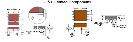
For surface mount we offer a variety of “Tab” leads for various requirements and sizes. For smaller parts, the “J” or “L” Dual Inline package is typically used to allow designers to minimize the land area required. Generally the “J” leads add .100” (.050”/side) to package length. The “L” leads add .025”-.050” to the height by wrapping under the chip.
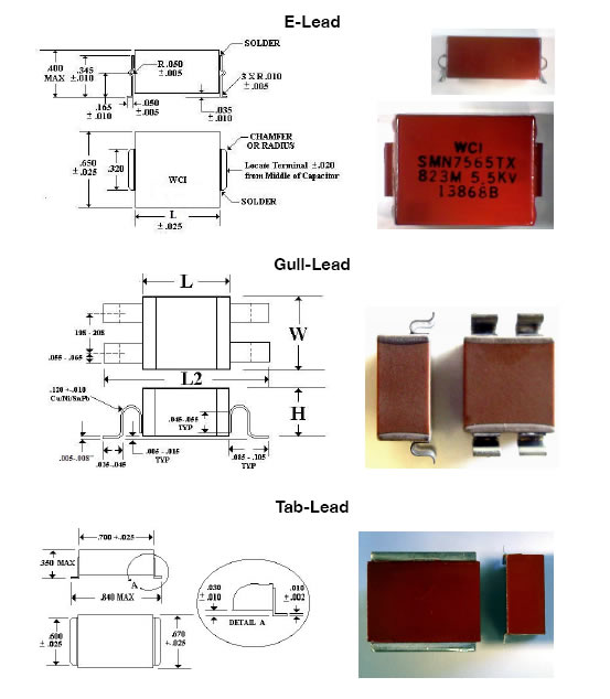
We also have a variety of custom leads, most Cu/Sn/Pb tabs. Some with “flex” bends for larger, higher reliability stress conditions. Our “E” lead and Gull-wing are examples with the gull wing taking up the most real estate, but with extreme reliability, and multiple configurations at .200” center spacing. We can also custom design an attachment method to meet your special requirements.
A variety of protective coatings are available depending upon application. For N2200 we use a red urethane varnish. For N2200 with an integrated bleed resistor and all other dielectrics we have available a clear, high temperature, high voltage, and moisture resistant protective coating. Please consult the factory for recommendations.
Ordering Information
| Prefix | Case Size | Encapsulation | Dielectric | Capacitance | Tolerance | Termination | Voltage | Suffix |
| SMN | 3840 | T | R | 124 | K | D | 102 | -R300 |
|
SM - Surface Mount SMN - Surface Mount w/ Testing SMS - Special Solder required - Sn95Sb05 |
Chip Size |
E = E Lead G = Gull Lead J = J Lead L = L Lead T = Tab Lead |
N = NPO R = N2200 X = X7R See Dielectric Characteristics for full list |
Capacitance Value Code in pF 1st two digits significant, 3rd the power of ten i.e.: 102 = 1000pF |
F = ±1% G = ±2% J = ±5% K = ±10% M = ±20% Z = +80%/-20% V = +100% |
A = Ag D = PdAg |
Voltage Code 1st two digits significant, 3rd the power of ten i.e. 102 = 1000V |
-A MIL-PRF-49467 -NM No Marking -NC No Coating -R#### = Bleed Resistor in MΩ -X### = Special Thickness |
Dielectric Codes
| Dielectric Code | Material |
Temperature Coefficient Please see Dielectric Characteristics for more information |
| N | COG/NPO | -55°/+125°C |
| N | COG/NPO | Hi Temp -55°/+250°C |
| R | N2T | -55°/+125°C/ ±500pm |
| R | N2T | Hi Temp -55°/+250°C |
| X | X7R/BR | BR -55°/+125°C |
| X | X7R/BR | Hi Temp -55°/+250°C |
| Y | Y5V | Y5V -30°/+85°C |
Prefixes
| Prefix | Description |
| WC | Standard |
| WCN |
Non standard Requirements High Temperature High Reliability |
| WCR | RoHS Compliant |
| HT | High Temperature (Potted Units) |
| HTN | High Temp w/ High Reliability Testing (Potted Units) |
| SM | Surface Mount |
| SMN | Surface Mount with High Reliability Testing |
| SMS | Special Solder required (Sn95Sb05) |
Capacitance Tolerance Codes
| Code | Tolerance |
| F | ± 1% |
| G | ± 2% |
| J | ± 5% |
| K | ± 10% |
| M | ± 20% |
| Z | +80%/-20% |
| V | + 100% |
Suffixes
| Suffix | Description |
| -A | MIL-PRF-49467 |
| -NM | No Marking |
| -NC | No Coating |
| -R ### | Bleed Resistor |
| -X### | Special Thickness |